Author: M Abo Bakar Aslam
8x1 Multiplexer (MUX)
A 8x1 Multiplexer (MUX) is a digital combinational circuit that selects one of eight input signals and forwards it to a single output line. The selection of input is controlled by three selection lines.
1. Truth Table - 8x1 Multiplexer
Suppose inputs are Input-0 to Input-7 and selection lines are S2, S1 and S0. The outputs are represented as out-0 to out-7.
Total Number of Rows = 2^(number of selection lines) = 2³ = 8
| Inputs | S2 | S1 | S0 | Output |
|---|---|---|---|---|
| Input-0 ... Input-7 | 0 | 0 | 0 | Input-0 → out-0 |
| Input-0 ... Input-7 | 0 | 0 | 1 | Input-1 → out-1 |
| Input-0 ... Input-7 | 0 | 1 | 0 | Input-2 → out-2 |
| Input-0 ... Input-7 | 0 | 1 | 1 | Input-3 → out-3 |
| Input-0 ... Input-7 | 1 | 0 | 0 | Input-4 → out-4 |
| Input-0 ... Input-7 | 1 | 0 | 1 | Input-5 → out-5 |
| Input-0 ... Input-7 | 1 | 1 | 0 | Input-6 → out-6 |
| Input-0 ... Input-7 | 1 | 1 | 1 | Input-7 → out-7 |
2. Boolean Expression for Output
As there is only one output, we will derive its Boolean expression.
Output = out-0 + out-1 + out-2 + out-3 + out-4 + out-5 + out-6 + out-7
Output = Input-0 S2' S1' S0' + Input-1 S2' S1' S0 + Input-2 S2' S1 S0' + Input-3 S2' S1 S0 + Input-4 S2 S1' S0' + Input-5 S2 S1' S0 + Input-6 S2 S1 S0' + Input-7 S2 S1 S0
3. Circuit Diagram
a. Block Diagram Representation
Multiplexer is commonly represented using a block diagram.

b. Using Basic Gates
The circuit diagram of 8x1 MUX can be implemented using AND, OR, and NOT gates.
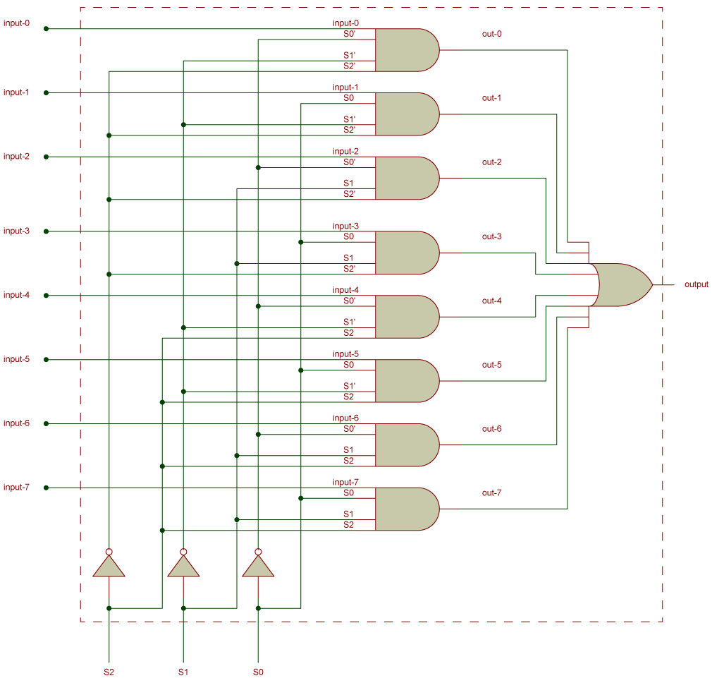
Circuit becomes more complex as we move from 2x1 to 8x1 MUX So we need to build MUX using some other logic i.e., 8x1 MUX using SMALL MUX.
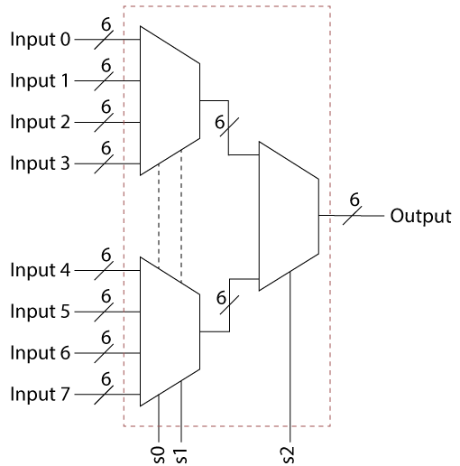
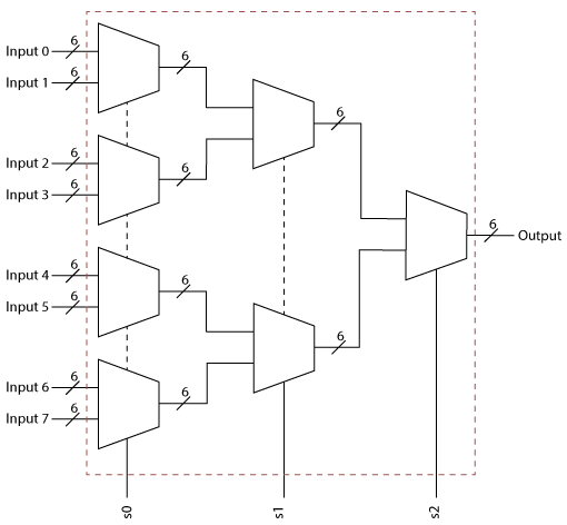
4. Building 8x1 MUX using 2x1 MUX
5. Building 8x1 MUX using both 2x1 and 4x1 MUX