Author: M Abo Bakar Aslam
Multiplexer (MUX)
A Multiplexer (MUX) is a digital combinational circuit that selects one of many input signals and forwards the selected input to a single output line. The selection of input is controlled by selection lines. Moreover, each inputs can contain multiple bits (1 or more bits).
We are explaining this lesson by using simplest type of MUX i.e., 4x1 MUX

1. Properties
- A Multiplexer selects one input from multiple inputs.
- It has n selection lines to control the selection.
- Total inputs = 2ⁿ, where n is the number of selection lines.
- It produces only one output.
- It is also known as a Data Selector.
2. Truth Table - 4x1 Multiplexer
Suppose inputs are Input-0, Input-1, Input-2, Input-3 and selection lines are Selection-1 and Selection-0. Each row of the output are named as out-0, out-1, out-2 and out-3
Total Number of Rows = 2^(number of selection lines) = 2^2 = 4
| Inputs | Selection-1 (S1) | Selection-0 (S0) | Output |
|---|---|---|---|
| Input-0, Input-1, Input-2, Input-3 | 0 | 0 | Input-0 → out-0 |
| Input-0, Input-1, Input-2, Input-3 | 0 | 1 | Input-1 → out-1 |
| Input-0, Input-1, Input-2, Input-3 | 1 | 0 | Input-2 → out-2 |
| Input-0, Input-1, Input-2, Input-3 | 1 | 1 | Input-3 → out-3 |
3. Boolean Expression for Output
As there is only one output, we will create a Boolean expression for this output.
Output = out-0 OR out-1 OR out-2 OR out-3
Output = out-0 + out-1 + out-2 + out-3
Output = Input-0 S1' S0' + Input-1 S1' S0 + Input-2 S1 S0' + Input-3 S1 S0
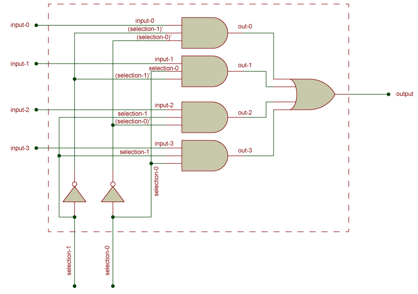
4. Circuit Diagram
a. Using Basic Gates
The circuit diagram can be implemented using AND, OR, and NOT gates.
b. Block Diagram Representation
Multiplexer is commonly represented using a block diagram.
5. Applications of Multiplexer
- Used in data routing in communication systems.
- Used in digital systems for signal selection.
- Used in time-division multiplexing.