Author: M Abo Bakar Aslam
2x1 Multiplexer (MUX)
A 2x1 Multiplexer (MUX) is the simplest form of a multiplexer that selects one of two input signals and forwards it to a single output line. The selection of input is controlled by a single selection line.
1. Truth Table - 2x1 Multiplexer
Suppose inputs are Input-0 and Input-1 and selection line is S. The outputs are represented as out-0 and out-1.
Total Number of Rows = 2^(number of selection lines) = 2¹ = 2
| Inputs | Selection (S) | Output |
|---|---|---|
| Input-0, Input-1 | 0 | Input-0 → out-0 |
| Input-0, Input-1 | 1 | Input-1 → out-1 |
2. Boolean Expression for Output
As there is only one output, we will derive its Boolean expression.
Output = out-0 OR out-1
Output = out-0 + out-1
Output = Input-0 S' + Input-1 S
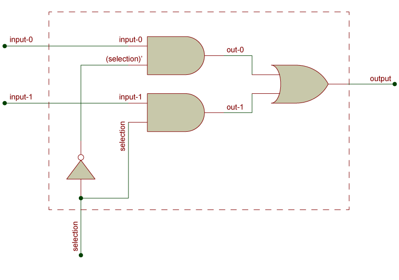
3. Circuit Diagram
a. Using Basic Gates
The circuit diagram of 2x1 MUX can be implemented using AND, OR, and NOT gates.
b. Block Diagram Representation
Multiplexer is commonly represented using a block diagram.
