Author: M Abo Bakar Aslam
Half Adder
A Half Adder is a fundamental digital circuit that performs addition of two binary bits. It produces two outputs: Sum and Carry. The Sum represents the least significant bit, while Carry represents the overflow.
1. Properties
- A Half Adder adds two single-bit inputs.
- It produces two outputs: Sum (S) and Carry (C).
- Sum is obtained using XOR operation.
- Carry is obtained using AND operation.
- It does not consider carry input from previous stage.
2. Truth Table - Half Adder
Suppose two bits are named as A and B.
Total Number of Rows = 2^(number of inputs) = 2^2 = 4
Total Numbers: 0, 1, 2, 3
| A | B | Carry (C) | Sum (S) |
|---|---|---|---|
| 0 | 0 | 0 | 0 |
| 0 | 1 | 0 | 1 |
| 1 | 0 | 0 | 1 |
| 1 | 1 | 1 | 0 |
3. Boolean Experssions for All Outputs - Sum and Carray
As there are two outputs (carry and sum). We will create two Boolean expressions. Each question will be based on two inputs. We will use 2-variable K-Map becuase there are two inputs for each of both outputs (Boolean expressions).
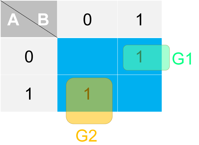
a. Sum - Boolean Expression
We placed only 1s in the K-Map and create equation accordingly.
Sum = AB′ + A′B = A ⊕ B
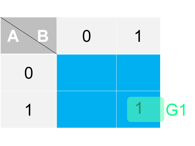
b. Carry - Boolean Expression
We placed only 1s in the K-Map and create equation accordingly.
Carry = AB
4. Circuit Diagram
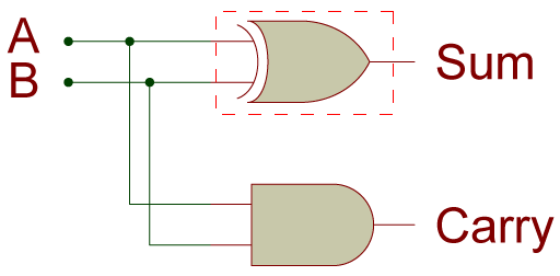
a. Using XOR - Circuit Diagram
The circuit diagram is created by using above equations. We didn't recreate inputs and all expressions (carry and sum) are using same inputs.
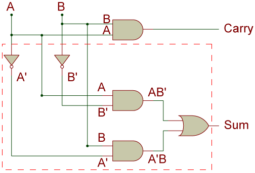
b. Using Basic-Gates - Circuit Diagram
The circuit diagram can be created by using basic gates. But in this way, number of gates would be increaased