Author: M Abo Bakar Aslam
Full Adder
A Full Adder is an advanced digital circuit that performs addition of three binary bits. It produces two outputs, i.e., Sum and Carry. The inputs include two significant bits and one carry input from the previous stage.
1. Properties
- A Full Adder adds three single-bit inputs.
- It produces two outputs: Sum (S) and Carry (C).
- Inputs are usually denoted as A, B, and Carry-in (Cin).
- It considers carry input from previous stage.
- It is constructed using two Half Adders and one OR gate.
2. Truth Table - Full Adder
Suppose three bits are named as A, B and Cin.
Total Number of Rows = 2^(number of inputs) = 2^3 = 8
Total Numbers: 0, 1, 2, 3, 4, 5, 6, 7
| A | B | Cin | Carry (C) | Sum (S) |
|---|---|---|---|---|
| 0 | 0 | 0 | 0 | 0 |
| 0 | 0 | 1 | 0 | 1 |
| 0 | 1 | 0 | 0 | 1 |
| 0 | 1 | 1 | 1 | 0 |
| 1 | 0 | 0 | 0 | 1 |
| 1 | 0 | 1 | 1 | 0 |
| 1 | 1 | 0 | 1 | 0 |
| 1 | 1 | 1 | 1 | 1 |
3. Boolean Experssions for All Outputs - Sum and Carray
As there are two outputs (carry and sum). We will create two Boolean expressions. Each question will be based on three inputs. We will use 3-variable K-Map becuase there are three inputs for each of both outputs (Boolean expressions).
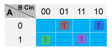
a. Sum - Boolean Expression
We placed only 1s in the K-Map and create equation accordingly.
Sum = A'B'Cin + A'B C'in + A B' C'in + A B Cin
Sum = (A'B' + AB)Cin + (A'B + AB')C'in
Sum = (A ⊕ B)'Cin + (A ⊕ B)C'in
Sum = A ⊕ B ⊕ Cin
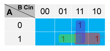
b. Carry - Boolean Expression
We placed only 1s in the K-Map and create equation accordingly.
Carry = AB + BCin + ACin
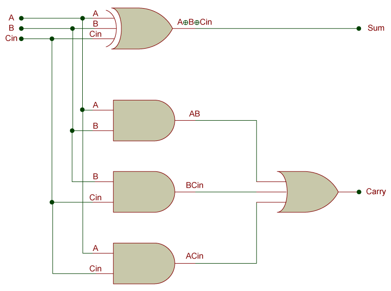
4. Circuit Diagram
a. Using Simplified/Minimized Expressions - Circuit Diagram
The circuit diagram is created by using XOR Gate.
b. Using Half Adders - Circuit Diagram
Firstly notice below examples for working of two half adders for addition of three bits (A, B and Cin). The circuit diagram can be created by using two Half Adders
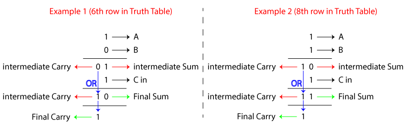
The circuit diagram can be created by using two Half Adders
