Author: M Abo Bakar Aslam
De-Multiplexer (DEMUX)
A De-Multiplexer (DEMUX) is a digital combinational circuit that takes a single input signal and forwards it to one of many output lines. The selection of output is controlled by selection lines. Moreover, each output can contain multiple bits (1 or more bits).
We are explaining this lesson by using simplest type of DEMUX i.e., 1x4 DEMUX

1. Properties
- A De-Multiplexer distributes one input to multiple outputs.
- It has n selection lines to control the output selection.
- Total outputs = 2ⁿ, where n is the number of selection lines.
- It has only one input.
- It is also known as a Data Distributor.
2. Truth Table - 1x4 De-Multiplexer
Suppose input is Input and selection lines are Selection-1 and Selection-0. The outputs are named as out-0, out-1, out-2 and out-3
Total Number of Rows = 2^(number of selection lines) = 2^2 = 4
| Input | Selection-1 (s1) | Selection-0 (s0) | Outputs |
|---|---|---|---|
| Input | 0 | 0 | out-0 = Input, out-1 = 0, out-2 = 0, out-3 = 0 |
| Input | 0 | 1 | out-0 = 0, out-1 = Input, out-2 = 0, out-3 = 0 |
| Input | 1 | 0 | out-0 = 0, out-1 = 0, out-2 = Input, out-3 = 0 |
| Input | 1 | 1 | out-0 = 0, out-1 = 0, out-2 = 0, out-3 = Input |
3. Boolean Expression for Output
As there are multiple outputs, we will create Boolean expressions for each output.
out-0 = Input s1' s0'
out-1 = Input s1' s0
out-2 = Input s1 s0'
out-3 = Input s1 s0
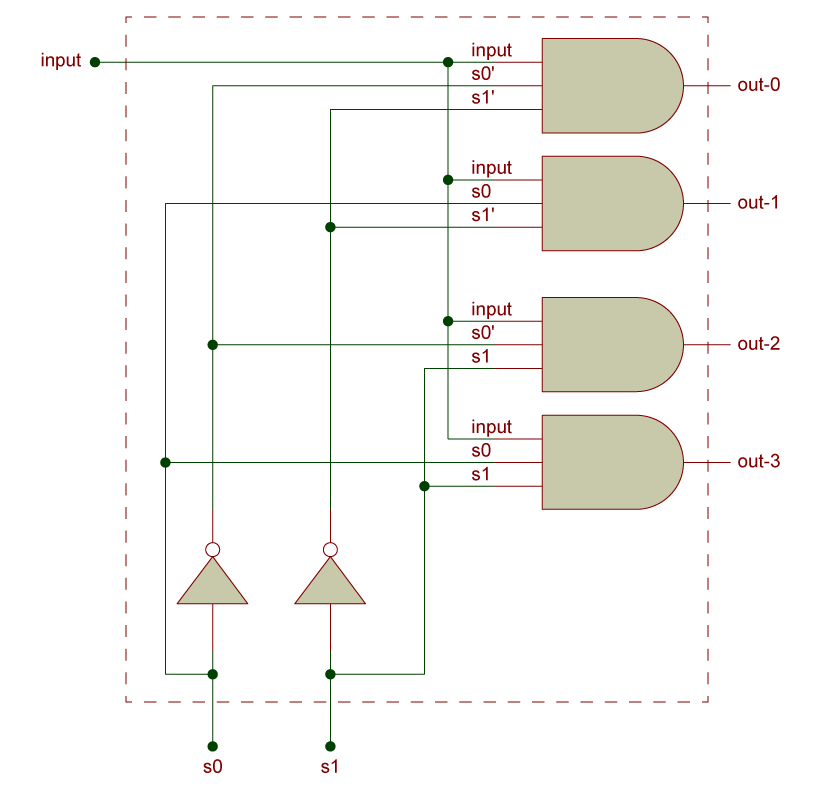
4. Circuit Diagram
a. Using Basic Gates
The circuit diagram can be implemented using AND and NOT gates.
b. Block Diagram Representation
De-Multiplexer is commonly represented using a block diagram.
5. Applications of De-Multiplexer
- Used in data distribution systems.
- Used in communication systems for routing signals.
- Used in memory addressing and decoding circuits.