Author: M Abo Bakar Aslam
BCD to 7-Segment Decoder
BCD is Binary-Code-Decimal code that represents decimal-number by using 4-bit binary-number. in this lesson, you will learn to converts 4-bit binary-number to decimal-number format and decimal-number would be shown using only one 7-segment-disply.
1. SEVEN Segment
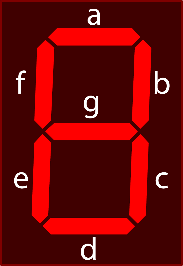
A 7-segment display is an electronic display device used to show numeric digits (0-9) using seven individual segments. It consists of seven LED segments arranged in a rectangular pattern. Each segment can be turned ON or OFF to form different numbers.
The segments are labeled as:
a, b, c, d, e, f, g (and sometimes dp for decimal point)
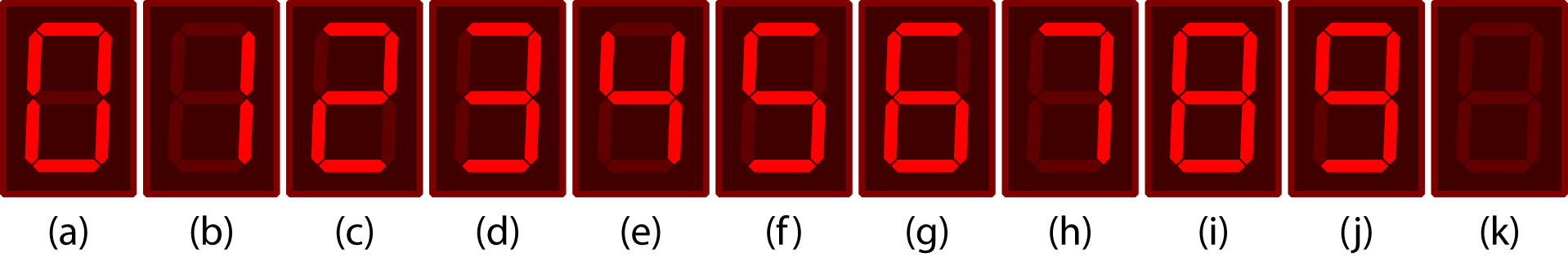
Using this segment, all possible outputs are mentioned in below figure. In case of not-possible-decimal-number, 7-segment-display is set as OFF (Fig. 1(k)).
2. Convesion from BCD to 7 segment Output
For 4-bit of binary number, there are fifteen possible decimal-numbers. All possible binary number and respective decimal numbers are shown in below Table. But there are some decimal-numbers (i.e., 10 to 15) that cannot be displayed using single SEVEN segment. Only 0-9 numbers can be displayed using one 7-segment-display. Figure numbers are also mentioned in which you can see output of the circuit for each user-input in binary format.
| X | Y | Z | W | Decimal | Figure |
|---|---|---|---|---|---|
| 0 | 0 | 0 | 0 | 0 | Fig. 1(a) |
| 0 | 0 | 0 | 1 | 1 | Fig. 1(b) |
| 0 | 0 | 1 | 0 | 2 | Fig. 1(c) |
| 0 | 0 | 1 | 1 | 3 | Fig. 1(d) |
| 0 | 1 | 0 | 0 | 4 | Fig. 1(e) |
| 0 | 1 | 0 | 1 | 5 | Fig. 1(f) |
| 0 | 1 | 1 | 0 | 6 | Fig. 1(g) |
| 0 | 1 | 1 | 1 | 7 | Fig. 1(h) |
| 1 | 0 | 0 | 0 | 8 | Fig. 1(i) |
| 1 | 0 | 0 | 1 | 9 | Fig. 1(j) |
| 1 | 0 | 1 | 0 | Not Possible | Fig. 1(k) |
| 1 | 0 | 1 | 1 | Not Possible | Fig. 1(k) |
| 1 | 1 | 0 | 0 | Not Possible | Fig. 1(k) |
| 1 | 1 | 0 | 1 | Not Possible | Fig. 1(k) |
| 1 | 1 | 1 | 0 | Not Possible | Fig. 1(k) |
| 1 | 1 | 1 | 1 | Not Possible | Fig. 1(k) |
3. Boolean Expression for 7-segment-display
For conversion, we used below truth table. User-inputs are named as X, Y, Z and W. Most-Significant-Bit (MSB) is named as X and Least-Significant-Bit (LSB) is named as W. While, Middle-bits are named as Y and Z from left to right. These names would be used in Boolean expression.
This table shows that:
-
When user-input is 0000, then 0 should be displayed in 7-segment-display because 0000 is binary of 0 with 4-bits. To display 0, G should be set as 0 (OFF) and all other LEDs (A, B, C, D, E and F) should be 1 (ON).
-
When user-input is 0001, then 1 should be displayed in 7-segment-display because 0001 is binary of 1 with 4-bits. To display 1, LEDs for A, D, E, F and G should be set as 0 (OFF), and LEDs for B and C should be 1 (ON).
-
When user-input is 0010, then 2 should be displayed in 7-segment-display because 0010 is binary of 2 with 4-bits. To display 2, LEDs for A, B, D, E, G should be set as 1 (ON), and LEDs for C and F should be 0 (OFF).
-
When user-input is 0011, then 3 should be displayed in 7-segment-display because 0011 is binary of 3 with 4-bits. To display 3, LEDs for A, B, C, D and G should be set as 1 (ON), and LEDs for E and F should be 0 (OFF).
-
When user-input is 0100, then 4 should be displayed in 7-segment-display because 0100 is binary of 4 with 4-bits. To display 4, LEDs for B, C, F and G should be set as 1 (ON), and LEDs for A, D and E should be 0 (OFF).
-
When user-input is 0101, then 5 should be displayed in 7-segment-display because 0101 is binary of 5 with 4-bits. To display 5, LEDs for A, C, D, F and G should be set as 1 (ON), and LEDs for B and E should be 0 (OFF).
-
When user-input is 0110, then 6 should be displayed in 7-segment-display because 0110 is binary of 6 with 4-bits. To display 6, LEDs for A, C, D, E, F and G should be set as 1 (ON), and LEDs for B should be 0 (OFF).
-
When user-input is 0111, then 7 should be displayed in 7-segment-display because 0111 is binary of 7 with 4-bits. To display 7, LEDs for A, B, and C should be set as 1 (ON), and LEDs for D, E, F and G should be 0 (OFF).
-
When user-input is 1000, then 8 should be displayed in 7-segment-display because 1000 is binary of 8 with 4-bits. To display 8, all LEDs (A, B, C, D, E, F and G) should be set as 1 (ON).
-
When user-input is 1001, then 9 should be displayed in 7-segment-display because 1001 is binary of 9 with 4-bits. To display 9, LEDs for A, B, C, D, F and G should be set as 1 (ON), and LEDs for E should be 0 (OFF).
| User Input | 7-Segment Display | |||||||||
|---|---|---|---|---|---|---|---|---|---|---|
| X | Y | Z | W | A | B | C | D | E | F | G |
| 0 | 0 | 0 | 0 | 1 | 1 | 1 | 1 | 1 | 1 | 0 |
| 0 | 0 | 0 | 1 | 0 | 1 | 1 | 0 | 0 | 0 | 0 |
| 0 | 0 | 1 | 0 | 1 | 1 | 0 | 1 | 1 | 0 | 1 |
| 0 | 0 | 1 | 1 | 1 | 1 | 1 | 1 | 0 | 0 | 1 |
| 0 | 1 | 0 | 0 | 0 | 1 | 1 | 0 | 0 | 1 | 1 |
| 0 | 1 | 0 | 1 | 1 | 0 | 1 | 1 | 0 | 1 | 1 |
| 0 | 1 | 1 | 0 | 1 | 0 | 1 | 1 | 1 | 1 | 1 |
| 0 | 1 | 1 | 1 | 1 | 1 | 1 | 0 | 0 | 0 | 0 |
| 1 | 0 | 0 | 0 | 1 | 1 | 1 | 1 | 1 | 1 | 1 |
| 1 | 0 | 0 | 1 | 1 | 1 | 1 | 1 | 0 | 1 | 1 |
| 1 | 0 | 1 | 0 | 0 | 0 | 0 | 0 | 0 | 0 | 0 |
| 1 | 0 | 1 | 1 | 0 | 0 | 0 | 0 | 0 | 0 | 0 |
| 1 | 1 | 0 | 0 | 0 | 0 | 0 | 0 | 0 | 0 | 0 |
| 1 | 1 | 0 | 1 | 0 | 0 | 0 | 0 | 0 | 0 | 0 |
| 1 | 1 | 1 | 0 | 0 | 0 | 0 | 0 | 0 | 0 | 0 |
| 1 | 1 | 1 | 1 | 0 | 0 | 0 | 0 | 0 | 0 | 0 |
Now we have to create Boolean expressions for A, B, C, D, E, F and G.
3.1. Boolean Expression for A
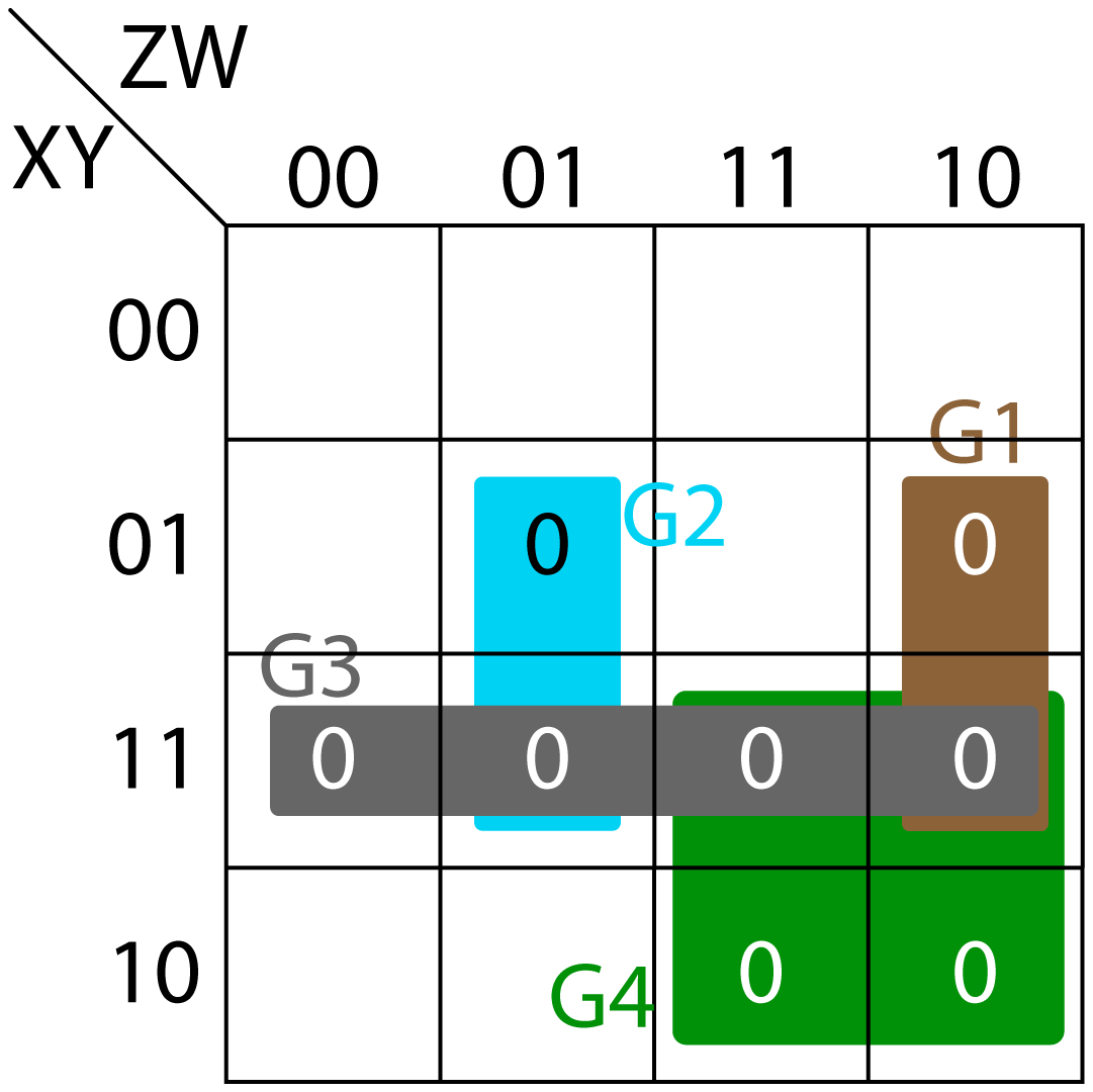
K-Map for value of column A is shown in below figure. In the map, four groups (G1, G2, G3 and G4) of 0's are created.
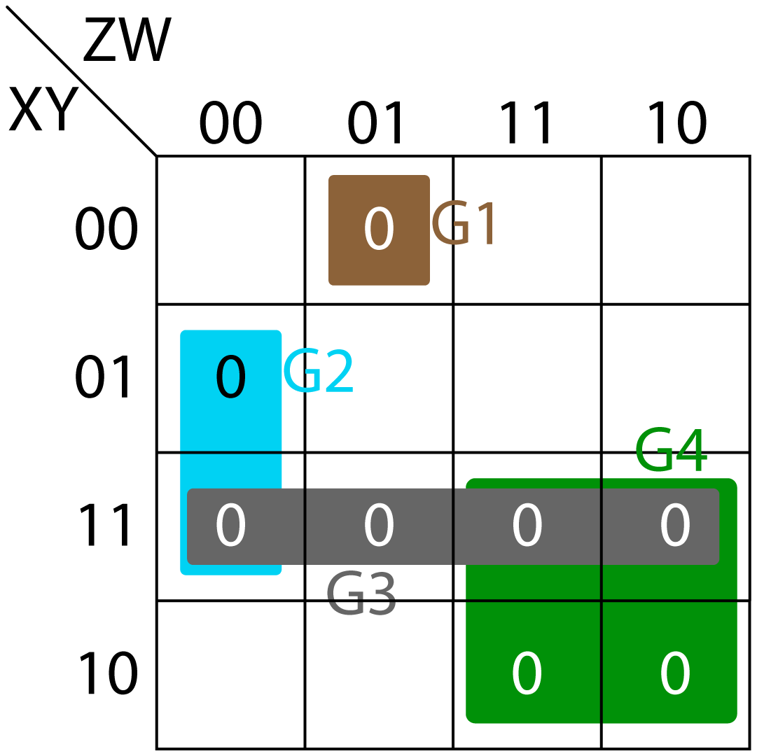
- Group G1 (brown color) creates (X+Y+Z+W')
- Group G2 (blue color) creates (Y'+Z+W)
- Group G3 (grey color) creates (X'+Y')
- Group G4 (green color) creates (X'+Z')
Therefore, Boolean expression of A is:
3.2. Boolean Expression for B
K-Map for value of column B is shown in Fig. 3. In the map, four groups (G1, G2, G3 and G4) of 0's are created.
- Group G1 (brown color) creates (Y'+Z'+W)
- Group G2 (blue color) creates (Y'+Z+W')
- Group G3 (grey color) creates (X'+Y')
- Group G4 (green color) creates (X'+Z')
Therefore, Boolean expression of B is:
3.3. Boolean Expression for C
K-Map for value of column C is shown in Fig. 4. In the map, three groups (G1, G2, and G3) of 0’s are created.
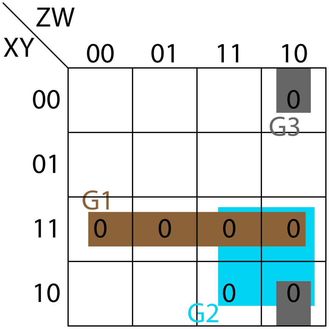
- Group G1 (brown color) creates (X'+Y')
- Group G2 (blue color) creates (X'+Z')
- Group G3 (grey color) creates (Y+Z'+W)
Therefore, Boolean expression of C is:
3.4. Boolean Expression for D
K-Map for value of column D is shown in Fig. 5. In the map, five groups (G1, G2, G3, G4 and G5) of 1’s are created.
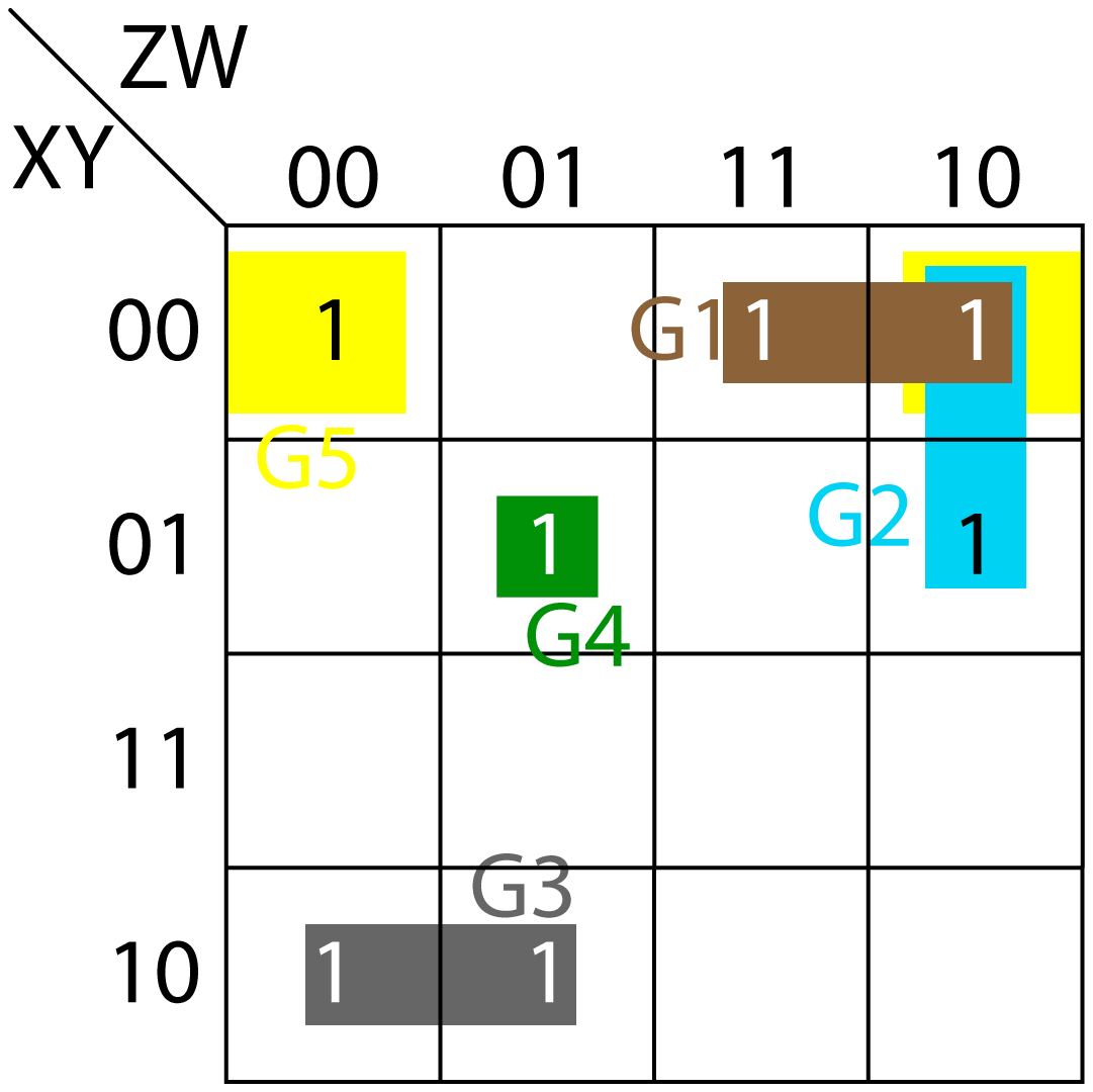
- Group G1 (brown color) creates (X'Y'Z)
- Group G2 (blue color) creates (X'ZW')
- Group G3 (grey color) creates (XY'Z')
- Group G4 (green color) creates (X'YZ'W)
- Group G5 (yellow color) creates (X'Y'W')
Therefore, Boolean expression of D is:
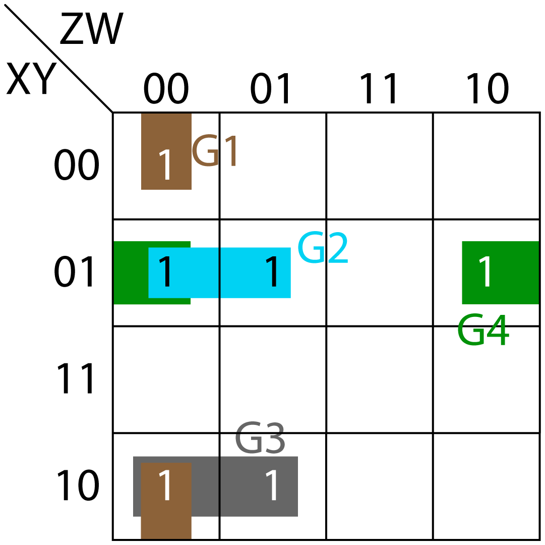
3.5. Boolean Expression for E
K-Map for value of column E is shown in Fig. 6. In the map, two groups (G1 and G2) of 1’s are created.
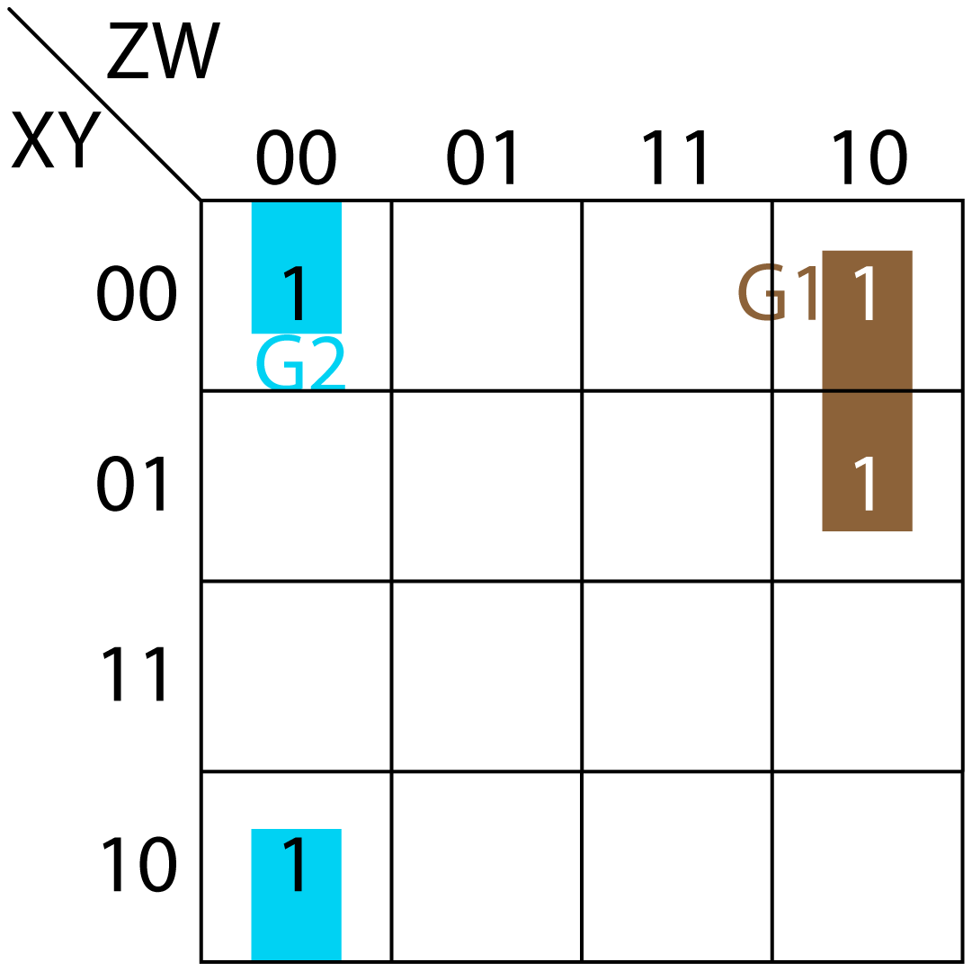
- Group G1 (brown color) creates (X'ZW')
- Group G2 (blue color) creates (Y'Z'W')
Therefore, Boolean expression of E is:
3.6. Boolean Expression for F
K-Map for value of column F is shown in Fig. 7. In the map, four groups (G1, G2, G3 and G4) of 1’s are created.
- Group G1 (brown color) creates (Y'Z'W')
- Group G2 (blue color) creates (X'YZ')
- Group G3 (grey color) creates (XY'Z')
- Group G4 (green color) creates (X'YW')
Therefore, Boolean expression of F is:
3.7. Boolean Expression for G
K-Map for value of column G is shown in Fig. 8. In the map, four groups (G1, G2, G3 and G4) of 1's are created.
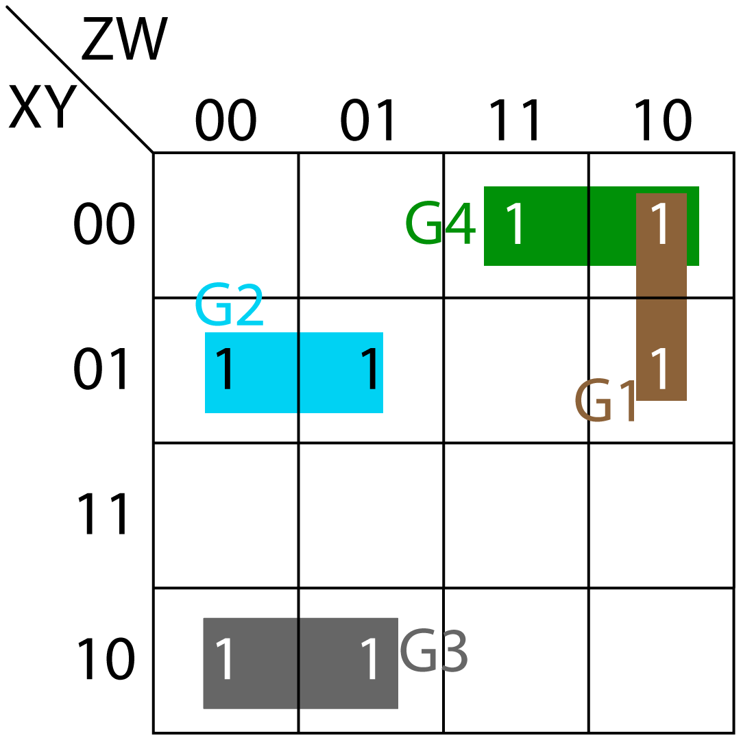
- Group G1 (brown color) creates (X'ZW')
- Group G2 (blue color) creates (X'YZ')
- Group G3 (grey color) creates (XY'Z')
- Group G4 (green color) creates (X'Y'Z)
Therefore, Boolean expression of G is:
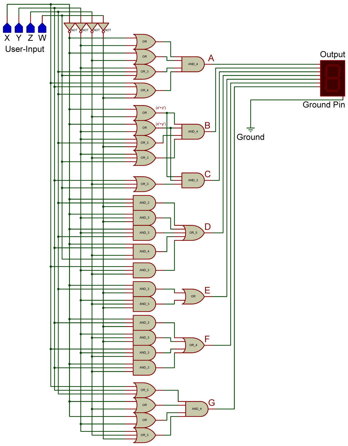
4 Circuit Diagram
Below figure shows the circuit diagram based on above equations. User-input is made using four bits through four logic-states (shown in blue color). Each logic-state can be either 0 or 1. The output for each user-input is also defined in above table.